DeeP MeLT
Arson's Lab
Numerical methods for multi-scale fracture propagation
Extended FEM, Cohesive Zone Models, Joint-enriched FEM
Predicting the occurrence of large-scale fractures (0.1m-10m) as the result of the interaction and/or coalescence of microscopic cracks is important to predict many instabilities in geomechanics. To understand the interaction between intra- and inter-crystalline crack propagation induced by stress-induced damage, viscous damage or fluid injection, we developed computational tools that allow simulation of the propagation of discrete fractures within a continuum damage process zone. We used 2D Joint-enriched FEM, Cohesive Zone Models (CZM) and the eXtended FEM (XFEM). The XFEM – based model was then enhanced to simulate multi-scale fracture propagation driven by fluid injection in transverse isotropic porous media.
- W. Jin, C. Arson, 2020. Fluid driven transition from damage to fracture in anisotropic porous media - a multiscale XFEM approach, Acta Geotechnica, DOI: 10.1007/s11440-019-00813-x.
- W. Jin, C. Arson, 2019. XFEM to couple nonlocal micromechanics damage with discrete mode I cohesive fracture, Computer Methods in Applied Mechanics and Engineering, DOI: 10.1016/j.cma.2019.112617.
- W. Jin, H. Xu, C. Arson, S. Busetti, 2017. A Multi-Scale Computation Tool Coupling Mode II Fracture Propagation and Damage Zone Evolution, International Journal of Numerical and Analytical Methods in Geomechanics, DOI: 10.1002/nag.2553.
- C. Zhu, A. Pouya, C. Arson, 2016. Prediction of viscous cracking and cyclic fatigue of salt polycrystals using a joint-enriched Finite Element Model, Mechanics of Materials, DOI: 10.1016/j.mechmat.2016.09.004.
Coupling damage poromechanics (FEM) with hydro-mechanical fractures (XFEM)
A numerical method was proposed to simulate multiscale fracture propagation driven by fluid injection in transversely isotropic porous media. Intrinsic anisotropy is accounted for at the continuum scale, by using a damage model in which four equivalent strains are defined to distinguish tension and compression, parallel and perpendicular to the layer. Nonlocal equivalent strains are calculated by integration, and are directly introduced in the damage evolution law. When the weighted damage exceeds a certain threshold, the transition from continuum damage to cohesive fracture is performed by dynamically inserting cohesive segments. Diffusion equations are used to model fluid flow inside the porous matrix and within the macro fracture, in which conductivity is obtained by Darcy's law and the cubic law, respectively. In the fractured elements, the displacement and pore pressure fields are discretized by using the XFEM technique. Interpolation on fracture elements is enriched with jump functions for displacements, and with level-set-based distance functions for fluid pressure, which ensures that displacements are discontinuous across the fracture, but that the pressure field remains continuous. After spatial and temporal discretization, the model is implemented in an open source object-oriented Finite Element Method package (OOFEM). A few simulations are carried out in plane strain. The results validate the formulation and implementation of the proposed model, and further demonstrate it can account for material and stress anisotropy.
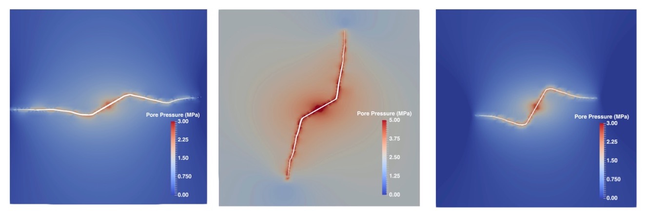
Pictures: Jin and Arson, 2020
Coupling continuum damage mechanics (FEM) with discrete fractures (XFEM)
We developed a multi-scale fracture propagation approach in the eXtended Finite Element Method (XFEM), which made it possible to simulate fracture propagation without assigning the fracture path a priori. Rigorous calibration procedures were established for the cohesive strength (related to the damage threshold) and the cohesive energy release rate, to ensure the balance of energy dissipated at the micro and macro scales. The XFEM-based tool is implemented in an open source objective oriented numerical package (OOFEM) and an arc length control resolution algorithm is used to avoid convergence issues that can be encountered otherwise during softening.
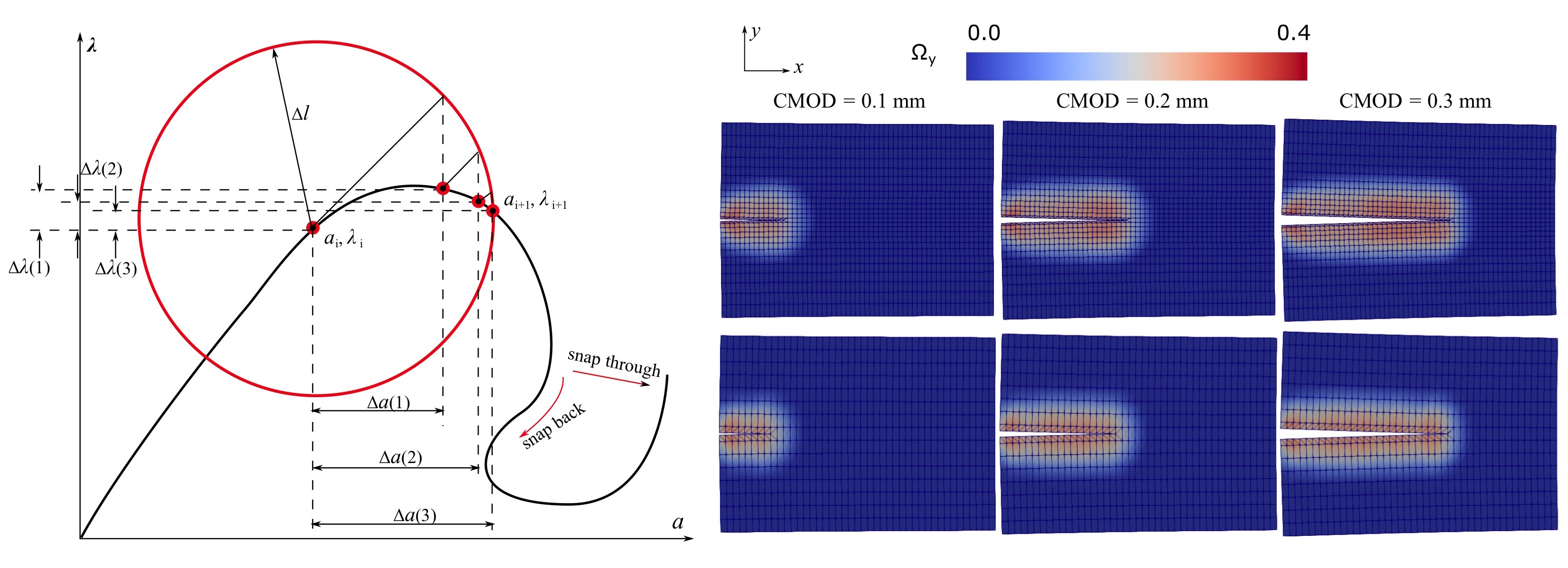
Pictures: Jin and Arson, 2019
Coupling continuum damage mechanics (FEM) with cohesive zone models (CZM)
We proposed a numerical method that couples a Cohesive Zone Model (CZM) and a Finite Element - based Continuum Damage Mechanics (CDM) model. The CZM represents a mode II macro-fracture, and CDM Finite Elements (FE) represent the damage zone of the CZM. The coupled CZM/CDM model can capture the flow of energy that takes place between the bulk material that forms the matrix and the macroscopic fracture surfaces. We used a continuum damage mechanics model in the Finite Elements and we calibrated it against triaxial compression tests performed on Bakken shale, so as to reproduce the stress/strain curve before the failure peak.
Based on a comparison with Kachanov's micro-mechanical model, we confirm that when the microcrack density value reaches 0.3, crack interaction can no longer be neglected. The CZM is assigned a pure mode II bilinear cohesive law. The cohesive shear strength of the CZM is calibrated by calculating the shear stress necessary to reach a CDM damage of 0.3 during a direct shear test. We find that the shear cohesive strength of the CZM depends linearly on the confining pressure. Triaxial compression tests are simulated, in which the shale sample is modeled as a FE CDM continuum that contains a predefined thin cohesive zone representing the idealized shear fracture plane. The shear energy release rate of the CZM is fitted in order to match to the post-peak stress/strain curves obtained during experimental tests performed on Bakken shale. We find that the energy release rate depends linearly on the shear cohesive strength.
We then used the calibrated shale rheology to simulate the propagation of a meter-scale mode II fracture. Under low confining pressure, the macroscopic crack (CZM) and its damaged zone (CDM) propagate simultaneously (i.e. during the same loading increments). Under high confining pressure, the fracture propagates in slip-friction, i. e. the debonding of the cohesive zone alternates with the propagation of continuum damage. The computational method is applicable to a range of geological injection problems including hydraulic fracturing and fluid storage, and should be further enhanced by the addition of mode I and mixed mode (I+II+III) propagation.
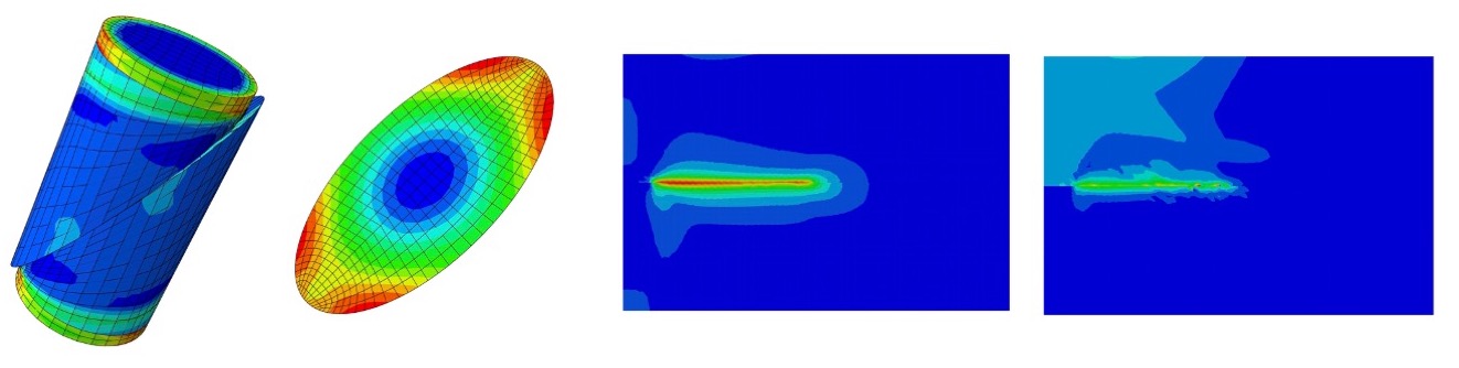
Pictures: Jin, Xu, Busetti and Arson, 2017
Coupling continuum damage mechanics (FEM) with joint elements (JE)
A new Joint-enriched Finite Element Method (JFEM) was proposed to predict viscous damage and fatigue in halite polycrystals in 2D. Different visco-plastic finite elements are used to represent grains of different orientations, and joint elements are used for modeling crack propagation. Simulations of uniaxial creep tests show that, as it could be predicted theoretically, viscous shear deformation in grains causes geometric incompatibilities. Numerical results also show that the transition between secondary and tertiary creep corresponds to inter-granular crack coalescence. The JFEM model captures the mechanical behavior of halite under cyclic loading, mainly: (a) Higher stress amplitude, lower confining stress, and lower loading frequency increase deformation and damage; (b) The polycrystal’s Young’s modulus decreases exponentially with the number of cycles; (c) The behavior is similar for different loading directions. Simulations with intra- and inter- granular joint elements show that most stress concentrations occur in intra-granular joints where several angular grains are in contact. Results of creep tests obtained with the JFEM are compared to those obtained with an inclusion-matrix model that accounts for damage accommodation due to grain breakage. Both the JFEM and inclusion-matrix models are calibrated against experimental creep tests to: (a) Produce a Young’s modulus of 23 GPa for the polycrystal; (b) Match secondary creep strain rates; (c) Match the time of tertiary creep initiation. In the inclusion-matrix model, the absence of grain geometric rearrangement results in a brutal failure just after the first grain breakage that triggers tertiary creep. Moreover, the JFEM model highlights the development of crack patterns upon viscous deformation. The JFEM is of great promise to understand complex phenomena of viscous accommodation coupled with grain interface debonding.
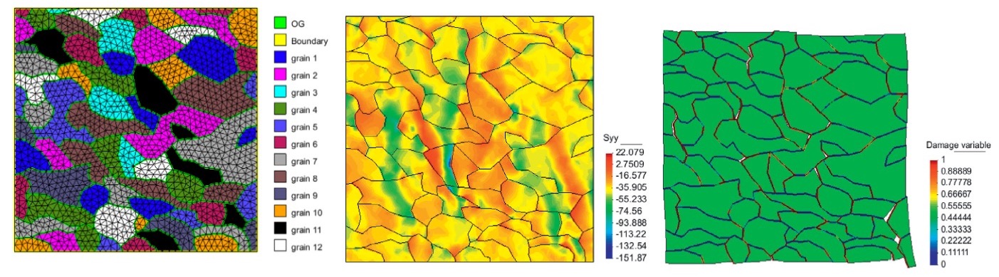
Pictures: Zhu, Pouya, Arson, 2016